This Programmer is powered by the RS-232 and it works with RS-232 levels at only < ±8.6V. It programs PIC12C5XX, 12C67X, 24CXX, 16C55X, 16C61, 16C62X, 16C71, 16C71X, 16C8X, 16F8X and ISO-CARD's with ASF. Other serial programmable chips by adapter.
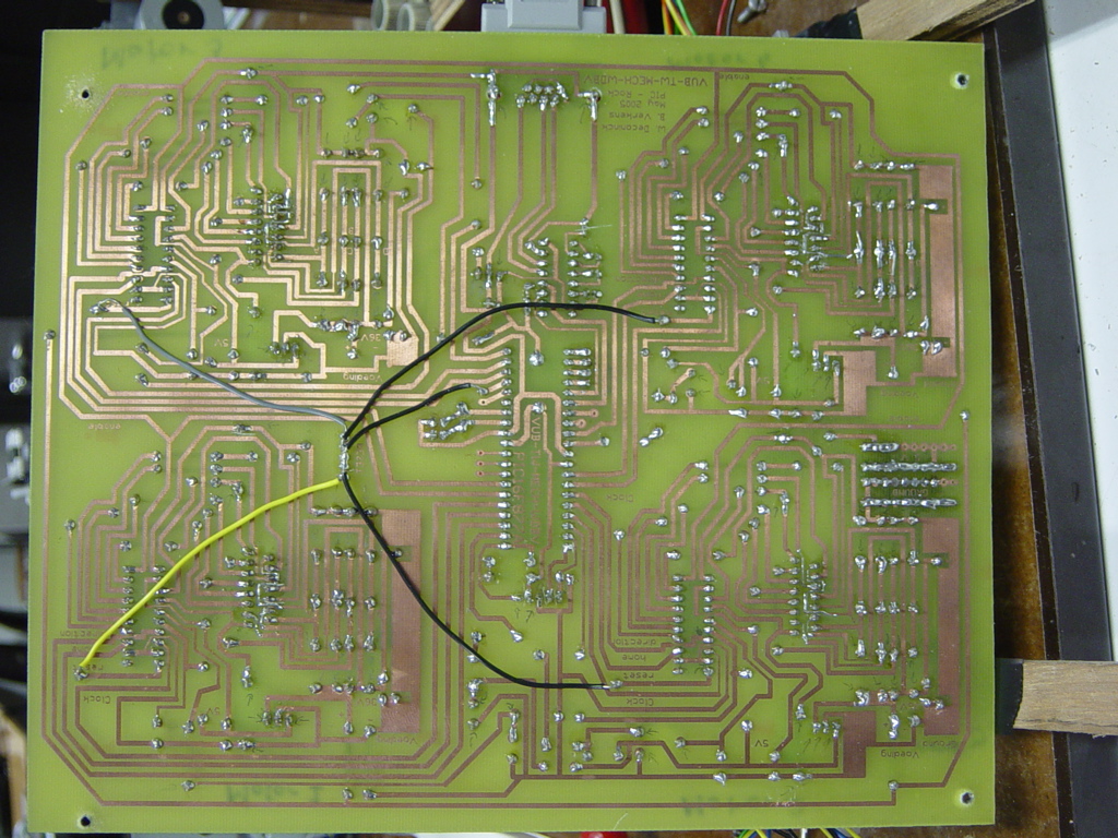
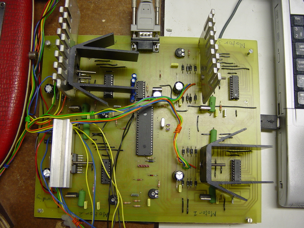

How to connect the wires.
Schematic

The high Vpp is obtained by using negative voltage to drive the chip. The voltage is stabilized with zener diodes. They do not need voltage drop as if a voltage regulator, or has much offset current. This makes it possible to use extra low input voltage. Transistor driver guarantee output level > ±3V.

Features: Utilities now work on Dos, Windows 3.1, Windows 95, Windows 98 and are expected to work on all other operating systems. All software does modemcheck to ensure that modems flash are not programmed by programmer, e.g. if you forgot to swap cable between programmer and modem. It is now possible to program more chips at same time using more of the communication port's while multitasking under Windows. The software automatic optimize delay for cable length and works with modem cables up to 100m. It use the RS232 controler chip only, and does not invoke use of other timers. Also short programming pulses are now hardware controled. Laptops only tested with PIC16C8x and 24Cxx.

The Programmer supports ICSP, In-Circuit Serial Programming.

D5 and D7 may be replaced by a BC557B. Emitter to MCLR and Collector to Vss.

EEPROM adapter for this programmer. (Supports Automatic Switch Function and LC types.)
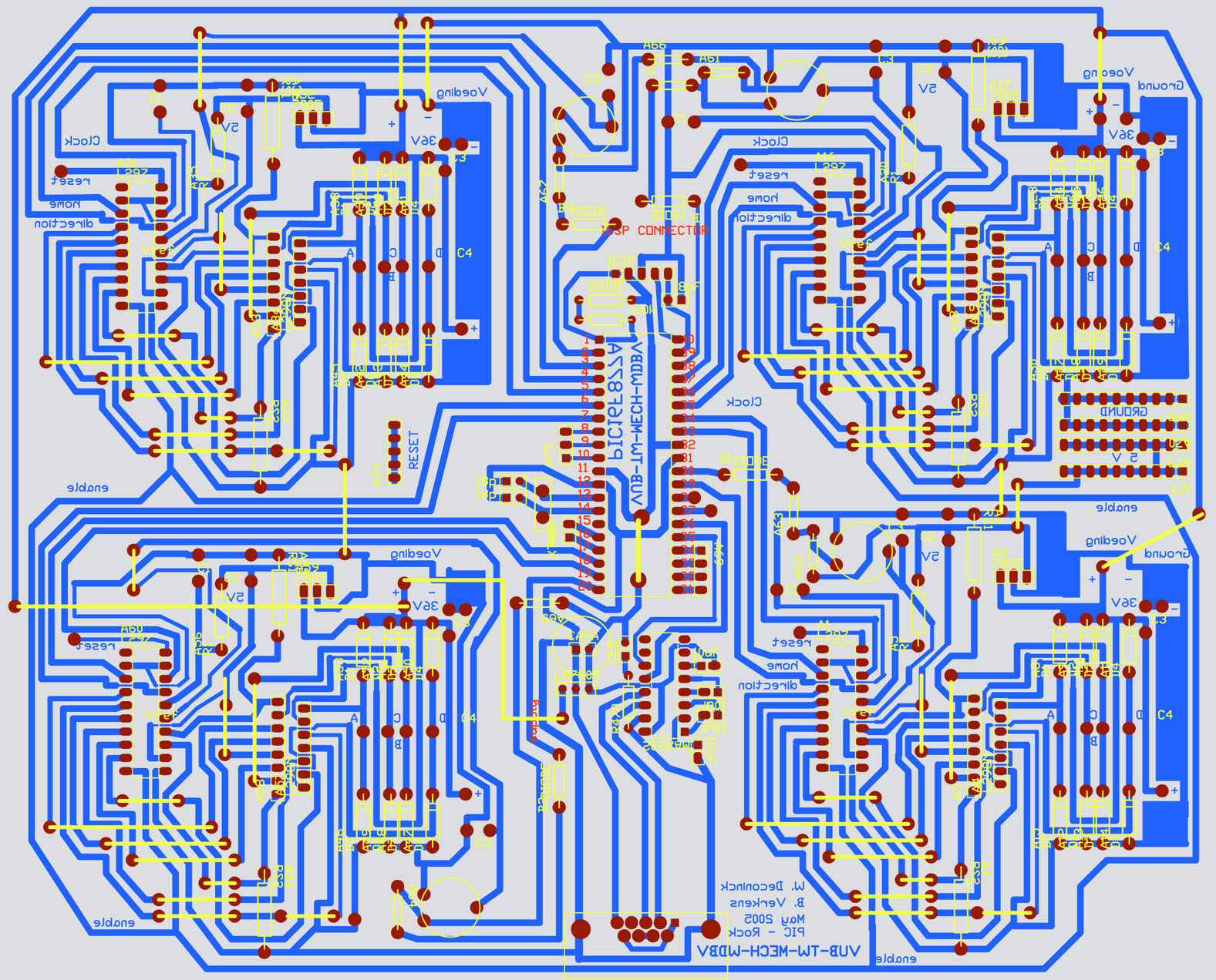
Schematic for the programmer.
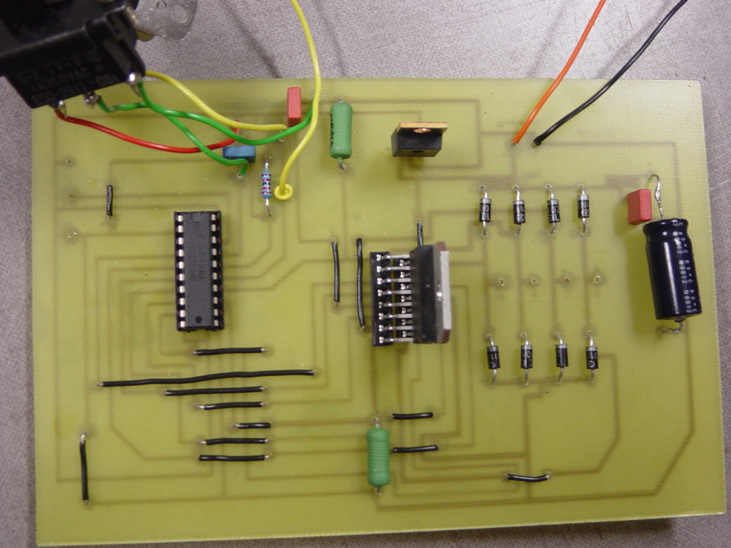
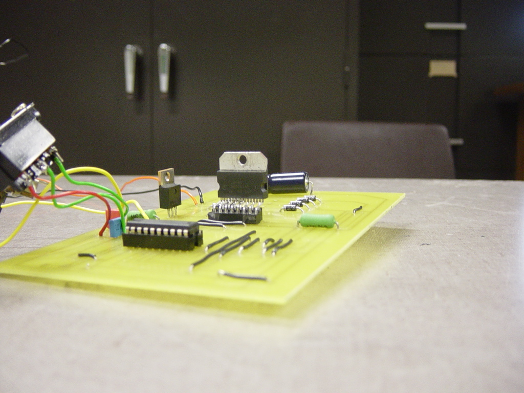
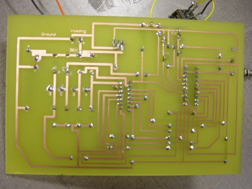
PCB for this programmer.
Detailed Funtional Describtion.

Download PIP02 beta driver, JDM84V33.ZIP (5K).
Works with windows too.

Download PIC16C84 utilities, PGM84V34.ZIP (38K).
Download PIC16C84 utilities, PGM84V35.ZIP (38K). (Beta version)
New PIC12C508 algorithme, P50XV21.ZIP (32K).
New PIC12C508 algorithme, P50XV22.ZIP (32K).
The utilities is inclusive source. If problems, then use slow version.
Updated 16 dec. 1999.

Most easy PIC-Programmer ever.
Most easy PIC-Programmer ever, w. 220V lamp edition.
Ultra lowcost for PIC16C84 only.
Simple programmer for PIC16C84 and 24Cxx only.

Applications:
How to use the programmer with In Circuit Serial Programming.
Connection to ISO-CARD with Automatic EEPROM Switch.

Which programmer to choose?

Problems?
You may need a diode in RS232 ground, but 24Cxx programming does not work when connecting a diode. Mail if diode is needed. I am not sure if it is computers that need the diode.
Schematic.

Always use last version of software. PGM84V29 has been improved to work better with laptops, and P50X has been updated to use a better algorithme. PGM84V32 and P50XV19 work better - and problems has been solved. P50XV20 is much slower, old versions was too fast.
New in PGM84V34: Small bug, according to Sebastian Edman and Malte Kiesel is corrected.
Also changed to be able to be compiled with free pascal. (Still able to be compiled with Borland Pascal). Last update: 16. dec 1999.

In case you develope your own routines, and do support my programmers, you do need to check voltage during read, and also programming voltages, since it depends on delays too. Test with more cable lengths are needed and must not result in programming / reading problems. Very slow interrupts, as e.g. exists in multitasking environments, must not make the voltages drop. An easy multitask test is to program more chips at same time using multiple ports.

Notice: If delays are too short, will PIC12C50X hang and need to be unpluged (Power removed) - and inserted again. Then it works. Use slower version (new versions or PROG50XS.BAT). If 3FFF at read, also use the slower versions. (READ50XS.BAT). Else does it hang, and reads blank.

Free routines: You may use my routines for the PIC-programmer in your own software, but only if your software is free- or if it is shareware. If any changes in my programming routines, it should be described with the documentation of your software package.

In the previous section, we show how we can drive the bipolar stepper motor and the unipolar stepper motor with the L293D chip. The Handy Board also has two on-board L293D chips which can drive up to 4 DC motors. As mentioned before, stepper motors are simply two(or more) coils that are driven in sequences. So, in theory, we can drive stepper motors using the motor drivers on the Handy Board directly.
Bipolar stepper motor

The pulse sequence of driving the bipolar stepper motor shown in the previous section can be interpreted as driving two different motors forwards and backwards. So, we can use the IC library functions for controlling the DC motors to drive the stepper motors, if we generate the correct pulse sequence. In the IC library, the function fd( ) is used to drive the DC motor in the forward direction and the function bk( ) is used to drive the DC motor in the backward direction. So, the fd ( ) fucntion will set one end of the corresponding motor high and the other end low. The bk ( ) function will just set the polarity of the motor in an opposite way. For example, the code fd(0) will set the the positive end of motor 0 to high (+5V) and the negative end of motor 0 to low (0V). So, we can generate the same pulse sequence as the one shown in the previous section, using a sequence of fd( ) and bk( ) functions. Suppose we plug coil 1 of the stepper motor into the motor 0 input of the Handy Board and coil 2 of the stepper motor into the motor 1 input of the Handy Board. The following C code fragment will generate the correct sequence of driving the stepper motor:

void main()
{ float x=0.001;
while(1){
fd(0);
fd(1);
sleep(x);
bk(0);
fd(1);
sleep(x);
bk(0);
bk(1);
sleep(x);
fd(0);
bk(1);
sleep(x);
}
}


Again, the variable x controls how long the processor should wait between each step and it determines the speed of the stepper motor. In the above example, the motor is set to rotate forever but you can use a for loop instead to set how much the motor should turn.
Unipolar Stepper Motor

Driving a unipolar stepper motor using the Handy Board directly is the same as driving the bipolar stepper motor with the Handy Board. You can use the same code fragment to drive the unipolar stepper motor. The only difference is you have to connect the extra common wire to the +5V supply.

Bipolar Stepper Motor

The L293D chip has 16 pins. Here is how each of the pins should be connected:

Pin 1, 9 Enable pins. Hook them together and you can either keep them high and run the motor all the time, or you can control them with you own controller(e.g. 68HC11).

Pin 3, 6, 11, 14 Here is where you plug in the two coils. To tell which wires correspond to each coil, you can use a mulitmeter to measure the resistance between the wires. The wires correspond to the same coil has a much lower resistance than wires correspond to different coils. (This method only applies to bipolar stepper motors. For unipolar stepper motors, you have to refer to the spec. sheet to tell which wires correspond to each coil.) You can then get one coil hooked up to pin 3,6 and another one hooked up to pin 11, 14.

Pin 4, 5, 12, 13 Gets hooked to ground.

Pin 8 Motor voltage, for the motors we are using, it is 12V.

Pin 16 +5V. It is the power supply of the chip and it's a good idea to keep this power supply separate from your motor power.

Pin 2, 7, 10, 15 Control signals. Here is where you supply the pulse sequence. The following is how you pulse them for a single-cycle (to move the motor in the opposite direction, just reverse the steps. i.e. from step 4 to step1):

Coil 1a

Coil 2a

Coil 1b

Coil 2b

Step 1

High

High

Low

Low

Step 2

Low

High

High

Low

Step 3

Low

Low

High

High

Step 4

High

Low

Low

High

In our example, we use the digital outputs of the Handy Board to generate the above pulse. The SPI pins on the connector on the middle right edge of the Handy Board can be configured as digital outputs. Do a poke(0x1009, 0x3c) to make them outputs; then they are mapped o the middle 4 bits of address 0x1008 (SS= bit 5, SCK=bit 4, MOSI=bit 3, MISO=bit 2). Poke to that address (0x1008) to set them.

Here is the code fragment to generate the pulses:

int address=0x1008;

float x=0.005;
int i;
int t=100;
poke (0x1009, 0x3c);
for(i=0; ipoke(address, 00001100);
sleep(x);
poke(address, 00011000);
sleep(x);
poke(address, 00110000);
sleep(x);
poke(address, 00100100);
sleep(x);
}

In the above code fragment, the variable x controls how much time the controller should wait between each steps and this consequently determines the speed of the motor. The variable t determines how many cycles controller should drive the motor and so this control the angular position of the shaft.

Unipolar Stepper Motor

Driving a unipolar stepper motor with the L293D is very similar to driving a bipolar stepper motor. The pulse sequence is the same and you can use the code fragment above to generate the pulse sequence. The only difference between driving a unipolar stepper motor and driving a bipolar stepper motor is that there is an extra wire in a unipolar stepper motor you have to hook up. You can hook it up to the +5V supply and the wires are hooked up in the same way as those in the bipolar stepper motor.

The L293D contains two H-bridges (for more information on H-bridges, click here.) for driving small DC motors. It can also be used to drive stepper motors because stepper motors are, in fact, two(or more) coils being driven in a sequence, backwards and forwards. One L293D can, in theory, drive one bi-polar 2 phase stepper motor, if you supply the correct sequence.

We are going to show how to drive a bipolar and a unipolar stepper motor with the L293D. The bipolar stepper motor and the unipolar stepper motor we used were bought from Jameco. (part# 105881 and 105890 respectively). Both of the bipolar and unipolar stepper motors are 3.6 degrees/step motors.

What does it do?

The L293D driver subsystem is particularly useful for use with d.c. motors because it can control two motors and can drive them forwards and backwards.

How does it operate?

L293D driver circuit

Click on the circuit diagram to download a Livewire file of the circuit that you can investigate and add to your own circuit.

The L293D IC has four input signals, labeled ‘a’, ‘b’, ‘c’ and ‘d’.

The driver boosts the current from these signals. The voltage signal at each output (‘a’, ‘b’, ‘c’ and ‘d’) is high or low when the corresponding input signal is high or low. But the current available from the output pin is much higher.

So the L293D is able to drive output devices requiring quite high currents of up to 600mA from each output pin.

The main advantage of the L293D is that, unlike a transistor, Darlington driver or MOSFET, it can drive a d.c. motor in forward or reverse.

It is particularly useful for work with PICs (hotlink to data sheet).

As well as controlling d.c. motors it is useful for work with stepper motors.


If the L293D is connected to two d.c. motors as shown on the left, and input signal ‘a’ is high and input signal ‘b’ is low, then current will flow out of output pin ‘a’, through the upper motor and into output pin ‘b’.

If input signal ‘c’ is low and input signal ‘d’ is high, then current will flow out of output pin ‘d’, through the lower motor and into output pin ‘c’. So the current in the lower motor will flow in the opposite direction to the current in the upper motor, and the motors will rotate in opposite directions.

Current can only flow in one direction (the direction of the arrow on the circuit symbol) through a transistor, Darlington driver or n-channel MOSFET, – which is why they cannot be used to reverse a motor.

When current is flowing out of the L293D this is called ‘sourcing’. When current is flowing into the L293D this is called ‘sinking’.

Possible applications

  • Driving a pair of motors in forward and reverse
  • Driving one motor in forward and reverse, and switching on up to two other output devices, such as a bulb or a buzzer
  • Controlling the movement of a stepper motor.

Making

Pins of the L293D driver

How part of the PCB might look

The blue lines show wire links on the component side.

Build and test the units that will provide the input signals before building the L293D driver.

Testing

Make sure that the signals going out (on the green PCB tracks) are the same (high or low) as the input signals (on the blue PCB tracks).

Fault finding

If there is a fault, check that the L293D is connected the right way round. Check the tracks and solder joints.

Alternatives

  • Relay – a double pole double throw relay can be used to reverse a motor, but it needs more components
  • Transistor – cheaper but cannot reverse a motor and provides less current
  • Darlington driver – cannot reverse a motor
  • MOSFET (Transducer driver) – cannot reverse a motor

Stepper motors are great to use in robotics. By energizing the coils in the motor in a particular sequence, a motor takes 48 or more small, precise steps to make one full revolution. If you are using two of these motors to drive your robot’s wheels, you can get good control over how far it travels by making the motors travel x many steps forwards or backwards. That’s assuming you can find stepper motor drivers, of course. I’ve always had problems finding good servo drivers. Once I was even reduced to using discreet components (say it isn’t so!) to drive my steppers.

Then I got my hands on the L293D motor driver chip (See motors part 1) and life got a lot easier. The L293D contains two H-bridges for driving small DC motors. Now the home-viewing audience might say: "Rob, it’s easy to drive DC motors. What I need to do is drive a stepper motor." No problem. After all, what is a DC motor but a coil and the L293D drives two of them backwards or forwards. That’s what stepper are - two (or more) coils being driven in a sequence, backwards and forwards. So one L293D can, in theory, drive one bi-polar 2 phase stepper, if you supply the sequence.

I found some close-out two-phase bi-polar steppers (part#117954) in the Jameco Catalog. For six bucks plus shipping I get a 7.5 degree stepper with 48 steps per revolution. The stepper motor runs at about 5 volts and pulls 800 milli-amps of current. That’s a lot of current so I can expect my chips to heat up. The way I fix the heat problem is by gluing a heat sink to the top of the chip. Any piece of metal three or four times the size of the chip will do. If things get real hot, I use a small fan to move air over the top of the heat sink.

STEPPER CONTROLLER SCHEMATIC

schem1.gif (5116 bytes)

I realize that Seattle has developed it’s own mutant breed of controller circuits, I think it’s based on the 68HC12, but I have successfully resisted all attempts to be lured to the dark side of the force and will continue to use the BS-2 (Basic Stamp II). Here is a real quick description of the L293D inputs:

1, 9 Enable pins. Hook them together and you can either keep them high and run the motor all the time, or you can control them with your own controller.

2,7,10, 15 Control the two coils. Here is how you pulse them for a single cycle:

STEPPER TABLE COIL A1 COIL B1 COIL A2 COIL B2
STEP 1 ON ON OFF OFF
STEP2 OFF ON ON OFF
STEP3 OFF OFF ON ON
STEP4 ON OFF OFF ON

3,6,11,14 Here is where you plug in the two coils. You want to ohm them out and make sure you get one coil hooked up to 3,6 and another one hooked up to 11,14.

4,5,12,13 Gets hooked to ground.

8 Motor voltage, usually about 6 volts.

16 +5 volts. It’s a good idea to keep this power supply separate from your motor power.

And here is the schematic to hook the BS-2 and the L293D together. Hey, I’ve even included the code!

schem2.gif (3719 bytes)

The software to program the Basic Stamp II can be found in stepprog.bs2

Notice that this single chip can handle a two coil stepper otherwise known as a two-phase stepper motor. If you want to do more than that, you need more chips. The cool thing is that if you have multiple steppers and you want to drive them one at a time (say on a PC board driller), it’s easy to have multiple L293Ds driven on the same line.

schem3.gif (3502 bytes)

BONUS! TROUBLE-SHOOTING SCENARIOS:

Let’s say you get this thing all hooked up to your microcontroller and it doesn’t work. Here are a couple of symptoms and what they point to as the cause. Since I’ve had the misfortune of experiencing each one of these problems personally, I thought I might be able to save you a little time and pain.

Symptom: The stepper motor shaft turns easily with fingers.

Cause/solution: No power to the circuitry, no power to the motor, or enable pin is low.

Symptom: Everything on, but motor is locked in one position.

Cause/solution: The L293D got the first position and that’s all. Check software, check connections, and check that the hard-wired ports match the software. You might want to pull out the logic probe.

Symptom: Everything on, stepper is shifting in position, but the motor won’t turn.

Cause/solution: The correct line isn’t getting pulsed. Either the software is trying to pulse the wrong line, or the lines are connected incorrectly. First thing to do is slow the pulses way down. Next, try different combinations of the lines or software. You are looking for a pulse series that increments the motor continually in one direction.

Symptom: Motor pulses, but it’s erratic and sometimes changes direction. Using your fingers you can turn the shaft either direction even though you still feel a pulse.

Cause/solution: One of the coils isn’t energizing. Check your wiring and your software. You might want to put the circuit to the probe or unplug the motor and check the voltages.

Symptom: Motor pulses, but the direction is wrong.

Cause/solution: Reverse the pulse order in the software or turn the cable around.

Symptom: Circuit over-heats quickly without anything working. You hear a pop, see smoke, and one or more chips crack and/or turn to carbon.

Cause/solution: Congratulations! you have reversed one or more voltages and fried one or more components in your circuit!

snappy title for this tutorial! This is a quick guide with a bit of extra info that I’ve learnt along the way to getting this working, showing that we can:

A) Use a supplemental power source to power the motor
B) Use the L293D chip to drive the motor
C) Use a switch to change the direction of the motor

UPDATE: If you intend to use this for robotics then please check out this page here to get the most out of this chip – I actually found the SN754410 easier to work with that the L293D, its exactly the same apart from it can handle more current http://luckylarry.co.uk/2009/08/obstacle-avoidance-robot-build-your-own-larrybot/

What I’ve Learnt
Although I’ve only used 1 motor, it is possible to use 2 motors on a single L293D chip, of course you then have to compensate on the current accordingly to ensure enough juice for both motors under peak load. Remember that if you use 2 motors, the power source will be the same voltage but the current needed will be doubled – a good start is by altering how your batteries are connected in series or parallel.

“The L293D is a monolithic integrated, high voltage, high current, 4-channel driver.” Basically this means using this chip you can use DC motors and power supplies of up to 36 Volts, thats some pretty big motors and the chip can supply a maximum current of 600mA per channel, the L293D chip is also what’s known as a type of H-Bridge. The H-Bridge is typically an electrical circuit that enables a voltage to be applied across a load in either direction to an output, e.g. motor.

This means you can essentially reverse the direction of current and thus reverse the direction of the motor. It works by having 4 elements in the circuit commonly known as corners: high side left, high side right, low side right, and low side left. By using combinations of these you are able to start, stop and reverse the current. You could make this circuit out of relays but its easier to use an IC – The L293D chip is pretty much 2 H-Bridge circuits, 1 per side of the chip or 1 per motor.

The bit we really care about in all of this is the 2 input pins per motor that do this logic and these, more importantly for our needs, can be controlled from the Arduino board.

You also don’t have to worry about voltage regulation so much because it allows for 2 power sources – 1 direct source, upto 36V for the motors and the other, 5V, to control the IC which can be supplied from the Arduino power supply or since my motor power supply is only 6V I’m going to use this (if the motor supply was higher I would consider using a transistor or voltage regulator). The only thing to remember is that the grounding connection must be shared/ common for both supplies. Below you can see the pin layout for the chip and the truth table showing the output logic.

L293D Pin layout

Pin 1 Pin 2 Pin 7 Function
High Low High Turn clockwise
High High Low Turn anti-clockwise
High Low Low Stop
High High High Stop
Low Not applicable Not applicable Stop

Generally speaking most DC motors require a lot more current than the Arduino board can provide for instance the motor that I’m using needs around 5 to 6 Volts. Now I could use a 12 Volt power source for the Arduino, but then its going to drain quickly when it has to power everything, especially if I was to add in another motor and a couple of servos, so instead my Arduino runs off of my 9 Volt power supply I made. (here)

You’ll need a few capacitors in this circuit to smooth out the power load to the motors as much as possible to help avoid any spikes and stabalise the current. I’m using a 50 Volt 10 uF capacitor on the power supply – I suggest you do this as the bare minimum. You could also add in a capacitor for each motor that you use – something like a 220nF multilayer ceramic capacitor should be OK for the small motors.

Shopping List
10K Ohm resistor (Brown, Black, Orange, Gold)
50V 10uF Capacitor
6V DC motor
L293D motor controller/ driver chip (IC)
A switch (push, toggle etc..)
Arduino Deumilanove w/ ATMEGA328
Breadboard / Prototyping board
Jumper/ Connector wires
4x AA battery holder
4x AA batteries
Optional 220nF multilayer ceramic capacitor (Y5V)
Optional 9V power supply (here) or use the USB power for the Arduino

Building the circuit
First lets start with the 16 pins on the L293D chip and what we need to wire these to. You’ll see that its basically got 2 sides, 1 for each motor.

arduino-L293D-DC-motor-control-circuit

  1. Enables and disables the motor whether it is on or off (high or low) comes from the Arduino digital PWM pin 9
  2. Logic pin for the motor (input is either high or low) goes to Arduino digital pin 4
  3. Is for one of the motor terminals can be either +/-
  4. Ground
  5. Ground
  6. Is for the other motor terminal
  7. Logic pin for our motor (input is either high or low) goes to Arduino digital PWM pin 3
  8. Power supply for the motor, this should be given the rated voltage of your motor, so mine is from a 6V supply
  9. Enables and disables the 2nd motor on or off (high or low)
  10. Logic pin for the 2nd motor (input is either high or low)
  11. Is for one of the 2nd motor terminals can be either +/-
  12. Ground
  13. Ground
  14. Is for the 2nd motors other terminal
  15. Logic pin for the 2nd motor (input is either high or low)
  16. Connected to +5V, in this case the power from motor supply

You can see from my photos how I’ve placed the L293D and wired it according to the above pins. Next I have my switch on Arduino digital pin 2 and I have the GND pin from Arduino connected to the GND rail on my breadboard. I also add the capacitor in between the power supply – making sure that the negative and positive terminals are correctly aligned. Finally I complete the circuit by adding in wires to carry the current from one side of the breadboard to the other and I add in the motor and its power supply.

arduino-L293D-DC-motor-control

Uploading the code
So the final bit is to upload the sketch below to the board and give it a test :)

int switchPin = 2;    // switch input
int motor1Pin1 = 3; // pin 2 on L293D
int motor1Pin2 = 4; // pin 7 on L293D
int enablePin = 9; // pin 1 on L293D

void setup() {
// set the switch as an input:
pinMode(switchPin, INPUT);

// set all the other pins you're using as outputs:
pinMode(motor1Pin1, OUTPUT);
pinMode(motor1Pin2, OUTPUT);
pinMode(enablePin, OUTPUT);

// set enablePin high so that motor can turn on:
digitalWrite(enablePin, HIGH);
}

void loop() {
// if the switch is high, motor will turn on one direction:
if (digitalRead(switchPin) == HIGH) {
digitalWrite(motor1Pin1, LOW); // set pin 2 on L293D low
digitalWrite(motor1Pin2, HIGH); // set pin 7 on L293D high
}
// if the switch is low, motor will turn in the opposite direction:
else {
digitalWrite(motor1Pin1, HIGH); // set pin 2 on L293D high
digitalWrite(motor1Pin2, LOW); // set pin 7 on L293D low
}
}

After thoughts
My initial thoughts are of expanding this layout to include an additional motor perhaps. But more interestingly I think changing the switch to start/stop the motor, controlling the enable pin 1 on the L293D and then using a potentiometer to make use of PWM and control the speed as well as the direction of the motor.

This content is published under the Attribution-Noncommercial-Share Alike 3.0 Unported license.

Share and Enjoy: These icons link to social bookmarking sites where readers can share and discover new web pages.
  • Digg
  • del.icio.us
  • StumbleUpon
  • Reddit
  • TwitThis
  • Facebook
  • Google Bookmarks
  • MySpace
  • Technorati
  1. Arduino: Controlling the Robot Arm
  2. Arduino: Control a DC motor with potentiometer and multiple power supplies
  3. Obstacle avoidance robot – build your own larryBot
  4. larryBot – versions 0.1 to 0.5 lessons learned
  5. Arduino: Modifying a Robot Arm
  6. Arduino + Processing: Getting values from SRF05 ultrasound sensor & serial port
  7. Arduino: motion triggered camera
  8. Arduino: Basic Theremin meets Processing!
  9. Arduino + Processing: Make a Radar Screen to Visualise Sensor Data from SRF-05 – Part 1: Setting up the Circuit and Outputting Values
  10. 3 LED Crossfade with PWM and Arduino

It's perfect for robotics applications, with just 4 MCU lines you can make two motors move forwards and backwards and stop.

Last update: 28/02/08


Brief Circuit explanation:


This is an implementation of the L298 to drive motors and inductive loads up to 4A continuously. Initially the L298 contains 2 separate channels, each one capable of driving 2A loads. Connecting them in parallel as in the schematic makes a single 4A driver.

The two wire connections W1 and W2 are to control the direction of the motor according to that table:

Signal on W1 and W2
result/action
10
Motor turns clockwise
01
Motor turns anticlockwise
11
Motor breaks
00
Motor is free

The 2 transistors Q1 and Q2 act as an OR gate enabling the L298 if any of the two signals W1 or W2 are high. If both W1 and W2 are low (logic 0), the driver is disabled and provides a high impedance on its output, causing an eventually connected motor to move freely with its inertia.


C1 and C2 are 10 nF decoupling capacitors.

D1 to D4 are flyback diodes. Their forward current should correspond with the the expected load.


The two leads of the motor are directly connected to J1.

The circuit can be powered with 9 to 35V


Here is an implementation of this circuit on a PCB. This an actual picture of the motor drivers we used in the ROBOCON 2007 competition.

Notice how the heatsink is firmly attached to the driver. this protects the IC from eventually burning-up from stall currents.

Download the zip file for this project
containing the full schematic, PCB designs and datasheet of the L298 IC.

[note: i use ExpressPCB(FREEWARE) to design the schematics and the PCB]

Click L298 to view datasheet


Part No.L298

Description DUAL FULL-BRIDGE DRIVER

Download L298 Click to view

File Size 185.1 Kbytes / 13 Pages

Maker STMICROELECTRONICS [STMicroelectronics]

Homepage http://www.st.com/

The purpose of the electronic board is to control 4 bipolar stepper motors by means of a microcontroller. The used microcontroller is the PIC 16F877A.

So in fact 4 similar circuits had to be designed, 1 for each stepper motor. Some research on the web quickly brought us to a chip that would make things a lot easier:
The chip L297 is used and works together with the chip L298. A very detailed info about these chips can be found in the datasheets on the "links" page of this site.
The L297 is a handy chip because it has all the easy input ports. For example instead of sending a sequences of 4 bits, only a clock signal is required to make the stepper motor rotate. To make it rotate in opposite direction, it's not necessary to change the sequence but just change one input from the chip from 1 to 0 or vice versa. The chip can only be fed by 5V and cant produce a high current at its output. That's why it works in combination with the L298 chip. This is a power chip that has to be fed with a voltage of 5V, but is also fed through another port with a voltage between 5V and 32V, which is used to power the steppers. As you see these values are much higher. This way the motors can get the needed power. Because it's always better to work with only 1 supply, and the 2 chips had to be fed by different voltages, we had to use the L7805 chip which regulates its output voltage at 5V exactly, while its input can be nearly anything higher than 5V. We used some capacitors to make sure the noise on the voltage is stable.
The PIC microcontroller must be fed with 5V also, so another 5V regulator was used for the PIC. For safety reasons we fed each chip with a different regulator. They are really cheap and it makes sure we don't overload each regulator.
The main reason to use this circuit is also because there's a built-in chopper in the L297 chip. With this tool it's possible to control the amount of power the attached motor receives from the supply. The controlling of the L298 happens through the L297 chip which is in its turn controlled by the PIC microcontroller.
Following picture shows the schematic for 1 stepper motor.


The left chip on the schematic is the L297 and the right chip is the L298. As you can see the input port 18 on the L297 is the clock. The faster the clock, the faster the motor will work. Input port 19 can make us choose whether we use the motor in half step or full step mode. We always use full step mode, which delivers more power to the motors, while half step mode would give a smoother turning. Input port 10 is the enable port. If this port is set to 0 then the motors get zero power. Set this port to 1 and it will work again. Port 17 is the clockwise / counter clockwise port (CW/CCW). Switching its value makes the motor rotate in opposite direction. Port 20 is the RESET port. It must be set to zero. Else the motor will always receive the bit sequence " 1 0 1 0 " and block. This has no practical use for us. Port 15 is called Vref. When the voltage Vref is lower than the voltage it receives through port 13 and 14 (SEN1 and SEN2) the motor will receive less power due to the working of the chopper of the 297. So actually, port 15 enables the chopper mode. is very handy because it takes care of our problem that the motors shouldn't use much power when they're not moving and as explained in the motor part of the hardware page we can't just disable the motors when they don't have to move, since then they'll skip steps. These ports are the ports we control with the PIC microcontroller.
Port 3 called HOME is an output port on the L297 and gives a pulse every time the motor passes the sequence "1 0 1 0". This is useful to count the steps the motor has made. First we thought we could use this, so we made a connection with this and the PIC but it's of no practical use since the PIC already knows how many steps the motor makes since the PIC itself takes care of the clock-signal. We now just count the pulses we have given. The L297 then passes the 2 phases on to the L298 chip which then chops the output to the motors if asked from the PIC.

Port ENABLE on the L297 from each circuit is connected together with the PIC so that all the motors are enabled and disabled simultaneously. Also the RESET ports are connected together and controlled simultaneously.

Each motor is thus connected to the PIC by 6 connections: CLOCK, ENABLE, RESET, CW/CCW, VREF and HOME. Since home isn't used, it shouldn't be connected in later designs of this board. For the ENABLE and the RESET there is for both functions only 1 connection on the PIC for all 4 motors, so not many ports of the PIC are used for this. Each additional motor only uses up 3 additional ports on the PIC (HOME excluded) since ENABLE and RESET are connected to the same ports as for the first motor. This also demonstrates the use of the L297 chip because else there would be needed many, many more ports per motor: 4 for the 4 bit sequence signal, plus additional ports for the chopper function we would have to design ourselves.

This concludes the motor circuits.

Besides the 4 electronic circuits for the stepper motors there's also the matter of connecting the PC to the electronic board. This happens through a serial connection. So this had to be included in the electronic board as well.
Also the so called ICSP connection was added. The purpose of the ICSP connection is to program the PIC microcontroller without removing it from the electronic board. By these means it's possible to eliminate the danger of damaging the connections on the microcontroller that would occur by always removing and replacing the PIC on the board.
The ICSP connection and the Serial connection could be copied from a demo board made by Ronald Van Ham.

The making of:
First we wanted to test the schematic we found. So we made our test-board. Actually his is only used to control only 1 bipolar stepper motor, but instead of a PIC microcontroller to control the L297 chip we used switches and function generators. With this board we could test the abilities of the motors. Seeing if the motors are damaged, or strong enough, without having to program one bit in Assembler or Visual Basic.
This proved to be really handy.
The result of the board is shown here.

When we agreed on the motors we would use and the fact that the test-board works, we could confide in our abilities to make the larger board that would contain the PIC and the circuits for each motor.
The TraxMaker design of the board is given here.

After a LOT of soldering the result is something to be proud of:

This might look like a huge board, but if u look at the other side u can see that it really couldn't have been made more compact. At least we tried our very best to make it as compact as possible. A lot of effort was put in lots of ways to move "this part" up so that "that part" could be moved a little closer to "another part" so that the final result would be smaller. What must also be taken into account is the fact we have 4 big schematics included: 1 for each motor.
Compare the test-board with our final board and u can see how much we managed to compress everything together.
Since it's such a big board we double, triple checked all the connections and we were very pleased to see that the board worked perfectly. No single error in its design could be detected.

Here is still a picture of our voltage source. Which has to generate 12V and 7A to power all 4 motors.


The SGS Thompson L298 motor driver chip is a brute of a motor driver, designed for up driving 4 amperes at 46 volts.

The SGS Thompson L298 motor driver can power up to 4 amperes through two motors up to a maximum of 46 volts. This chip accepts standard TTL logic level inputs, but does require back-EMF protection diodes for chip protection.

We use this IC on our own ScoutWalker 1 walking robot kit for maximum power transfer to the motors.

Recently many kind of robot contests have being opened and some interesting reports of the challenge are found on the web. The Line Following is a kind of the robot contests to vie running speed on the line. I build a tiny line following robot which can run on the desk, moving the key board aside will do. It is for only a personal toy reduced its size less than one fifth compared to typical line following robots, not in formura. But I believe that it is suitable for home use in the small Japanese houses said that rabbit burrow...(^_^;. Of course I have also no time to take part in the robot contests :-(

About Line Follower

The line follower is one of the self operating robot that follows a line that drawn on the floor. The basic operations of the line following are as follows:

  1. Capture line position with optical sensors mounted at front end of the robot. Most are using several number of photo-reflectors, and some leading contestants are using an image sensor for image processing. The line sensing procss requires high resolution and high robustness.
  2. Steear robot to track the line with any steearing mechanism. This is just a servo operation, any phase compensation will be required to stabilize tracking motion by applying digital PID filter or any other servo argolithm.
  3. Control speed according to the lane condition. Running speed is limited during passing a curve due to friction of the tire and the floor.

There are two line styles, white line on the black floor and black line on the white floor. Most contest are adopting the first one in line width of between 15 and 25 millimeters.

Hardware

Mechanics

Right image shows bottom view and side view of the built line following robot. All mechanical and electrical parts are mounted on a proto board, and it also constitutes the chasis.

The line following robot is upheld in three points of two driving wheels and a free wheel. The driving wheels are made with a 7 mm dia ball bearing and a rubber tire. The free wheel is a 5 mm dia ball bearing attached loosely. To drive driving wheels, two tiny vibration motors that used for cellular phone, pager or any mobile equipment are used. Its shaft is pressed onto the tire with a spring plate, the output torque is transferred to the wheels.

The steearing mechanism is realized in differential drive that steear the robot by difference in rotation speed between the left wheel and the right wheel. It does not require any additional actuator, only controling the wheel speed will do.

Electronics

ControllerATmega8 (Atmel)
Line sensorSix photo-reflectors
Power supplyTwo CR2032 lithium cells
(One is for controller, the other is for motors)
MotorTwo micromotors for left wheel and right wheel
Dimensions45(L), 33(W), 12.5(H) [mm]
Weight15 grams (Body:8g, Cells:7g)
Performance53 centimeter per second at oval course

An Atmel ATmega8 is used for the controller and it is powered by a lithium coin cell. The other lithium coin cell is for only motors. Separating the power supply into two cells is to avoid accidental reset of the microcontroller due to voltage dip by motor start current. Six photo-reflectors are mounted at front end of the chasis. They sense reflection rate of the floor under them. Motors are driven in PWM to control rotation speed lineary.

Software

Using photo-reflectors

To detect a line to be followed, most contestants are using two or more number of poto-reflectors. Its output current that proportional to reflection rate of the floor is converted to voltage with a resister and tested it if the line is detected or not. However the threshold voltage cannot be fixed to any level because optical current by ambent light is added to the output current like the image shown right.

Most photo-detecting modules for industrial use are using modurated light to avoid interference by the ambient light. The detected signal is filtered with a band pass filter and disused signals are filtered out. Therefore only the modurated signal from the light emitter can be detected. Of course the detector must not be saturated by ambient light, this is effective when the detector is working in linear region.

In this project, pulsed light is used to cancel ambient light. This is suitable for arraied sensors that scanned in sequence to avoid interference from next sensor. The microcontroller starts to scan the sensor status, sample an output voltage, turn on LED and sample again the output voltage. The difference between the two samples is the optical current by LED, output voltage by the ambient light is canceled. The other sensors are also scanned the same avobe in sequence.

Signal processing of line detection

Right image shows the actual line posisiton vs detected line position in center value of 640. The microcontroller scans six sensors and calcurates the line position by output ratio of two sensors near the line. Thus the line position can be detected lineary with only six sensors. All the sensor outputs are captured as analog value that proportioning to reflection ratio, and the sensitivity have variety between each one of them. In this system, to remove the variations from the outputs, calibration parameters for each sensor can be held into non-volatile memory. This can be done with online mode. The microcontroler enters the online mode when an ISP cable is attached, and it can be controlled with a terminal program in serial format of N81 38.4kbps. S1 command monitors sensor values, and S2 command calibrates variation of sensor gain on the reference surface (white paper). The ATmega8 must be set to 8MHz internal osc.

Tracking control

The line position is compeared to the center value to be tracked, the position error is processed with Proportional/Integral/Diffence filters to generate steering command. The line folloing robot tracks the line in PID control that the most popular argolithm for servo control.

The proportional term is the commom process in the servo system. It is only a gain amplifire without time dependent process. The differencial term is applied in order to improve the responce to disturbance, and it also compensate phase lag at the controled object. The D term will be required in most case to stabilize tracking motion. The I term is not used in this project from following resons. The I term that boosts DC gain is applied in order to remove left offset error, however, it often decrease servo stability due to its phase lag. The line following operation can ignore such tracking offset so that the I term is not required.

When any line sensing error has occured for a time due to getting out of line or end of line, the motors are stopped and the microcontroller enters sleep state of zero power consumption.

Notes


Originally created by Craig Maynard for the Western Canadian Robot Games

PDF version of the Ruleset for the Line Follower Event

Please note: 2004 adjustments to rules are in blue text


Concept:

The line follow is a classic introductory robot design and requires a minimal amount of resources. (Go to your favorite search engine and enter "line following robot"). These robots can use microprocessor control or simple digital or analog control systems and are highly visual and entertaining to watch! A great event for re-programmed Mini-Sumos!

Description:

This event is intended to showcase basic sensor design and robot control systems in the form of a small autonomous robot which must follow a black line over a white surface. Points are awarded based upon the distance covered and the speed of the overall robot.

Robot Specifications:

The robots have no restrictions on size or power sources, but must be able to operate without cues or input from owner/operator. We recommend keeping your robot under 12" square, to fit past some of the obstacles with room to spare - aim for 9" or smaller. Penalties may be awarded to robots which are fundamentally unmodified retail kits: Kudo's to those whose robots are scratch-built and totally custom. Robots build from robot construction kits, like Lego Mindstorms or Meccano, are NOT penalized.

The Competition Platform:

line-follower-DSCN5988.jpg (64603 bytes)

The arena of operation consists of a white painted surface with a black line made from standard electrical tape. Lighting levels are unpredictable and the robot must be able to operate over a wide range of lighting conditions.

There will be several stages, each of increasing complexity. Completion of each stage adds to that competitors points score.

Special Notice: Dave Hylands was kind enough to do a very complete web document on the track used at the 2002 WCRG event. Check it out!

The Rules:

Follow the line as far and as fast as you can. The robot will be placed at a pre-assigned starting point and may be started by hand as directed by the judge. Once started your robot must navigate along a black line as quickly as possible.

As the course progresses the complexity of the line becomes more difficult and may include (but is not restricted to) the following distractions.

  • Gentle rounded corners

  • Sharp rounded corners

  • Sharp obtuse angles (greater than 90 degrees)

  • Sharp acute angles (less than 90 degrees)

  • Dark tunnels (make sure your robot can see in the dark and fit through the tunnel)

  • Gaps in the tape (robot might leave line and have to find it again )

  • Hills (both up and down)

  • Bumps (small cracks may exist on surface)

  • Distractions

  • Variations in line thickness

Robot operators are allowed to replace an errant robot on track but will suffer a penalty for each replacement.

A robot must have a positive score on the first (qualifying) stage before progressing to subsequent stages. (adjusted rule 2004)

The course layout will not be made available until the day of the event.

Scoring:

Each stage consists of approximately 3 m length of black tape.

Points Awarded / Penalized Description Example
100 points x (Robot-distance/Total-Stage-distance) A Percentage of 100 points is awarded depending on amount of each stage covered (to nearest 10 cm). Robot transits 30% of stage 1 : 30 points
100 points Bonus awarded for successful un-interrupted completion of entire stage. Robot navigates one stage to completion without handling... bonus 100 points
3000 points / (time to complete stage in seconds ) Points awarded to reward quicker robots. Timer runs even when robot leaves line and is replaced. Robot completes stage after 25 seconds: awarded 120 points.
75 point per stage attempted Robot is scratch built (See WCRS definition) Bonus points are awarded for the extra design effort.
-50 points per violation Picking up robot and replacing on line (at point where robot left line) Operator decides robot, which has left line, is unable to re-acquire. He/she moves robot back to line : 50 points per violation

Potential line following stages...